
Installing American Hard Bag Harley Saddlebag Amplifier Wire Harness

This article covers installation of several variations of saddlebag amplifier wire harnesses that we offer including some add on options. The wire harness that you receive may or may not have all of the harness parts described here. The harness that you have may or may not look exactly like the parts pictured here. Saddlebag wire harnesses can be used in either the left or right side bag. All variations of these harnesses allow you to install an amplifier in one saddlebag and drive speakers that are located outside of that saddlebag in other locations on the bike. This harness provides quick disconnects for all amplifier circuits and all connections are designed for water exposure, heat, and extreme vibration. These connections include power, ground, remote turn on, RCA, and speaker outputs.
Below you will find pictures and descriptions of the major components of this kit.
Bike Side Main Harness (Pic 1)
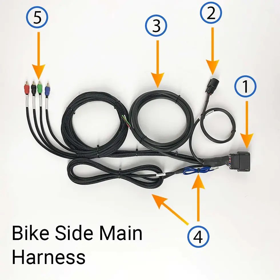
Black female multi pin connector. Connects to the bag side main harness.
Black female 2 pin connector. Connects to bag side connector for second bag speaker without amplifier.
Front speaker wire run. Connects to speakers in the fairing. 2 Channel versions will not have a front speaker wire run.
Remote Turn-On. Connects to DSP or radio (wherever the signal is coming from) at the front of the bike.
RCA inputs for amplifier. Connects to DSP or radio at the front of bike.
Bag Side Main Harness (Pic 2)
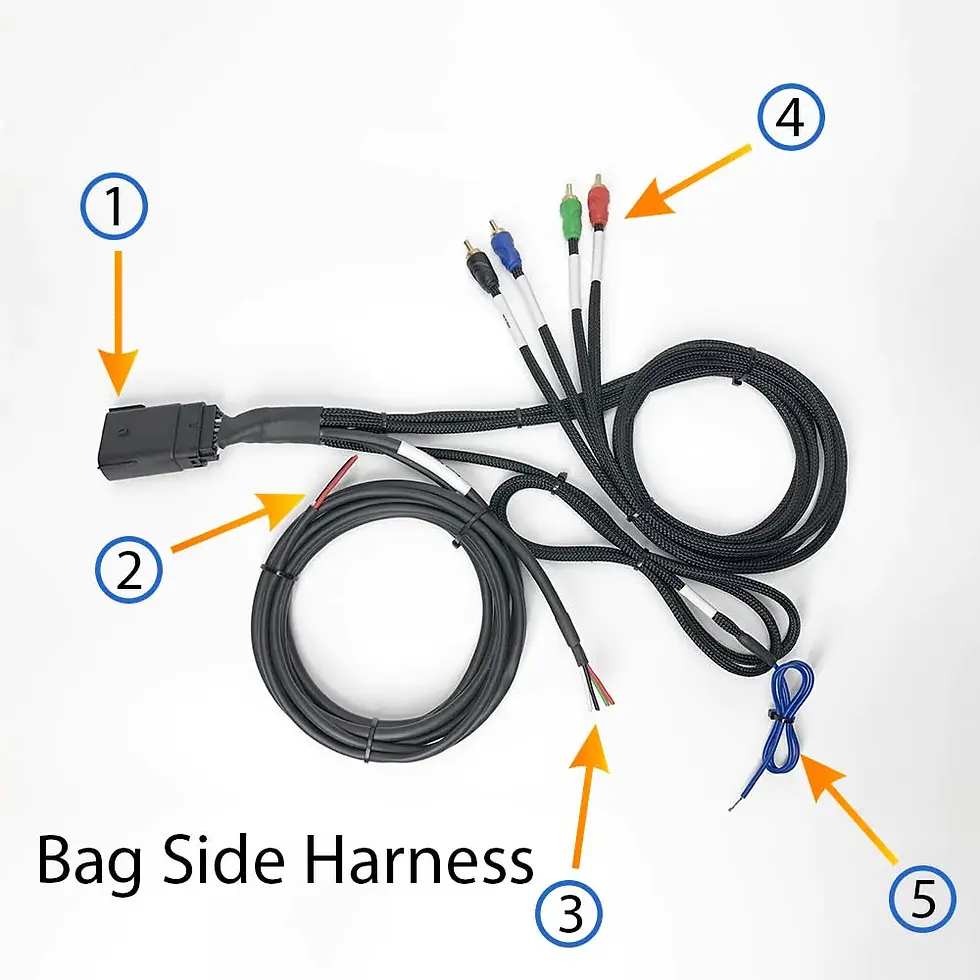
Black multi pin connector. Connects to bag side main harness.
Speaker connection for second bag speaker (speaker in bag without amplifier). Connects to amplifier output.Trim to length.
Speaker connection for front speakers. Connects to amplifier front outputs. Trim to length.
RCA inputs for amplifier in bag. Not all harnesses will have the RCAs integrated into the main plug. On many custom harnesses the RCAs are separate from the main harness so that they can easily be customized for the system.
Remote Turn-On. Connects to the amplifier remote input. Though this line can be cut down we recommend not cutting it shorter than the loomed section. Leave yourself a clean service loop so that the amplifier will be serviceable in the future.
Speaker Input Harness for Second Bag (Pic 3)

This harness is 6 ft long, which may seem excessive, but it is actually the perfect length for lid speakers. Read more about that in the installation details below. Connect this harness to the speaker in the bag without an amplifier. If using on woofers down low in the bag you can trim this cable down to whatever length you need.
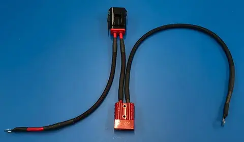
Bike Side Power Harness (Pic 4)
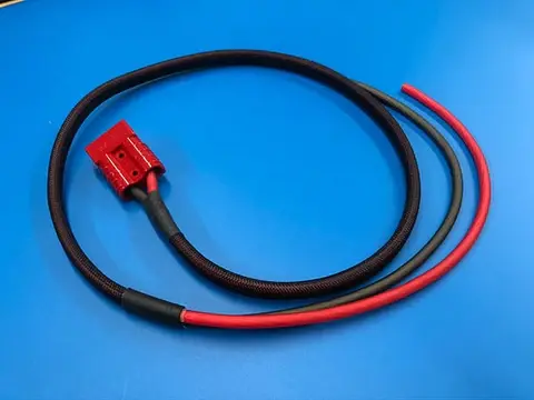
Bag Side Power Harness (Pic 5)

Notice that in the pic above the bags on the right have been taped to protect the paint and the bags have been clamped to the bench with a soft cloth under them. It is much easier to work on a bag that is clamped to the bench. This way the bag stays still as you work.
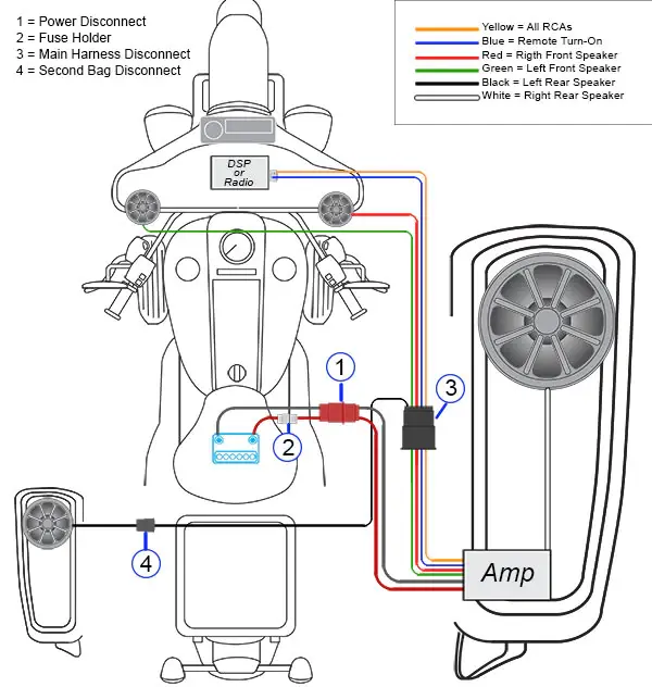
Overview Diagram
Note: Though this diagram shows the amplifier in the right side bag, this kit will work equally as well with the amplifier in either the left or right side bag. This harness even works for installing the amplifier in a tour pack.
Installation Step 1
Identify the main harness and the direction that all circuits will run on the bike (RCAs, turn-on, and speaker circuits). The main harness is made up of two distinct parts that contain remote turn-on, RCA and speaker circuits. Some custom harnesses will not have RCAs integrated into the main harness. We make them both ways.
The bike side harness. You can easily identify this part (see pic 1 above). The large multi pin connector has female pins as well as a two pin female connector for the second bag speaker. This harness runs from the side cover area in front of the bag in which you are installing the amplifier, up to the fairing as well as the second bag that does not contain the amplifier.
The bag side harness. You can easily identify this part (see pic 2 above). This side of the harness does not have a two pin connector for the second bag speaker. There is only one black multi pin connector on this harness and it has male pins. This harness runs from the side cover area where it connects to the bike side main harness, to the amplifier inside the bag. This harness contains all speaker connection circuits except any speakers that are in the same bag as the amplifier. Those speaker connections are made in the bag using the “extra speaker wire” that comes in your kit. No external disconnect is required for speakers that reside in the same bag as the amplifier. FOR EXAMPLE: A 4 channel harness will have three external speaker wire circuits. Two fairing speakers and one speaker wire run to the second bag that does not contain the amplifier.
Lay the Harness Out On the Bike.
Plug both the bike side and bag sides of the main harness together. Position the large black multi pin connectors under the side cover in front of the bag with the amp, in an area where it will be easily serviceable and will not interfere with any moving components of the bike. 4 channel kits will have a 4 conductor speaker wire run for the front fairing speakers. 2 channel kits will not have front speaker circuits. Route the fairing speaker wire cable, RCAs, and remote turn-on cables to the front of the bike.
Step 2
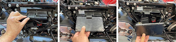
Route the cable with the 2 pin black plug (#2 in pic 1 above) to the opposite side of the bike and locate it in the side cover area in front of the bag without the amplifier. This is the connection for speakers in the second bag with no amp. The best way to do this is to remove the battery from the bike and route the cable either in front of or behind the battery. Do not route this cable over the top of the bikes frame. Unbolt the bike's fuse holder assembly on the clutch side of the bike.

This whole assembly can be unbolted by removing the two torx bolts. Once unbolted the assembly will still be connected to the bike by the wire harness. If you need more room to work you can cut the large zip tie that holds the main harness to the backside of the assembly. Be sure that you replace this zip tie when reassembling.

The BCM can be removed and wires can be routed through this area if needed. There is also lots of free space in there where you can mount fuse holders.
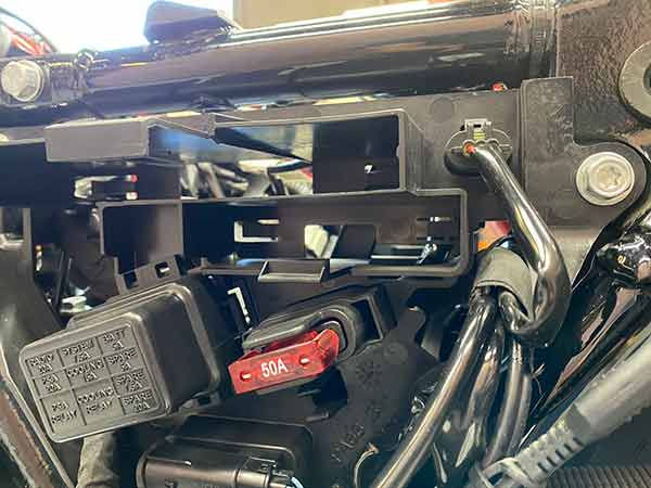

Notice in the pic above how the speaker plug (bottom plug circled) fits in there like its factory. Note that the amplifier fuse holder (circled top) is tucked under the BCM and also fits and looks like a factory part.
Step 3

Disconnect the bag side harness and route the cables into the bag that will contain the amplifier. To do this, drill a hole just large enough for all required cables to pass into the bag (about 1”). The hole should be located on the inside wall of the bag (the wall that faces the tire), about 2 inches from the bottom and two inches from the front. The wire inlets can be sealed with silicone or with foam gasket. Do not seal it up until you have finished the entire installation. Sealing the wire harnesses in place should be the very last thing you do. Notice that the chrome cap is angled back at the same angle as the front of the bag. This is done intentionally so that the cables form a bit of a loop backwards before bending to the side cover in the opposite direction. This slight loop gives the wire harness just enough slack so that the bag can be easily tilted back and disconnected for service but also keeps tension on the cable assembly so that the cables stay far away from the moving parts of the bike. Be sure to pre drill the screw holes before attempting to mount the chrome caps.

Step 4
Mount the fuse holder and make your battery connections. American Hard Bag saddlebag amplifier wire harnesses have a dedicated power harness section. This is a two piece harness that has a bike side (part 1) and a bag side (part 2). The bike side connects to the battery and provides a quick release power connector at the side cover in front of the saddlebag. The fuse holder should be located either in front of the battery or under one of the side covers under the seat. We always prefer that the fuse holder is zip tied under one of the side covers. The side cover location is an easily accessible and logical location for a fuse holder since that's where the factory Harley fuse boxes are.
Check the fuse holder and remove the fuse (if it has one in it) before installation.
Find a safe location for the fuse holder and zip tie it in place where it will not short out to a grounded surface, where it is easily accessible, and where the power leads will not become twisted, cut, or damaged.
Locate the power connector in the side cover area where the bag side of the harness can reach. Don’t leave too much slack or the side cover may be difficult to put back in place. Once situated, use a zip tie to tether the power input and output cables to a solid structure such as the frame or the factory fuse box structure.
Temporarily connect the bag side of the power harness to the bike side of the power harness so that you can be sure that the entire assembly fits and is well situated in the side cover area.
The ideal cable length from the wire exit point of the bag and the connectors is about 14 inches.

There is a lot of room for connections under and in front of the ABS module on the throttle side of the bike. Be sure to adjust the length of all cables so that the connectors all fit comfortably. If you leave the cables too long they will be difficult to put in place and get the side cover back on when you are done. If you have them too short you will not be able to make the connections. Take your time here. When done correctly the connections will be easily serviceable and the side cover will go back in place without any difficulty. Notice that the saddlebag cables run on the outside of the frame. There is plenty of room between the side cover and the frame for the cables.
Tips & Details
Speaker Cable & Connections
Red = Positive
Black = Negative
White = Left positive
Green = Left Negative

The speaker cable is a high quality oxygen free copper cable that has been designed to be very compact and friendly to run throughout the bike. The outer casing of these cables are made of a durable plastic that is friendly to strip and taylor to your particular installation. To strip the casing off, score the casing around the outside where you want to strip it down to. Then bend the cable and the casing will easily snap where it was scored. The cable has a nylon ripcord embedded into it that can be pulled on to split the casing away for you. Score and break off a small section of the casing near the end of the cable. This will expose the ends of the individual wires as well as a section of the ripcord. Use pliers to grab the ripcord and shear off the casing as needed.
The individual speaker wire conductors within this cable have a high grade thin walled PVC insulator that is designed to be a premium covering yet not add much to the diameter of the cable. The copper of these cables are 100% OFC, which is the very best for speaker cables. The end result is a whole lot of quality speaker cable in a very compact package.
Tip: The outer black casing of these cables is intentionally rigid. This makes the cables a lot nicer to route through the bike. You can heat the casing with a heat gun if you want to straighten a bent or twisted cable or if you want to custom shape a cable. A good example of when you would want to do this is when routing our speaker cables along the inside of the saddlebag.
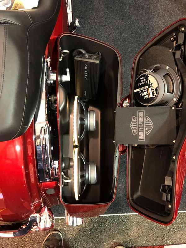
Connecting to Lid Speakers
When routing speaker, power, and RCA cables in a saddle bag the cables can be routed in a way that keeps them out of sight and out of harm’s way. In the pic below the saddlebag has 8 gauge power and ground, remote turn on, two subwoofer connections in the bag, one subwoofer connection exiting the bag, two speaker runs to the lid, and LED lighting for the subwoofers as well as the lid speakers. Most of the wiring is concealed under the two subwoofers and tucked between the amplifier and the inner wall of the bag. All of the amplifier connections enter the bag just forward of the shock tower and then take an immediate 90 degree turn towards the rear of the bag. Under the second subwoofer (rear) the cables make a 180 degree turn and loop back up to the amplifier at the front of the bag. This loop in the cables makes it possible to easily service the amplifier and get to all of the connections.
The saddlebag speaker input cables are 6ft long, which seems too long but is actually the perfect length for lid speakers. Instead of crossing the front of the saddlebag with the speaker cable, route it from the entrance point at the front inside corner, down the length of the bag to the far rear bottom edge. Bend the cable so that it flows around the rear bottom corner and comes back towards the front as it runs along the outside wall. Route the cable up high now and zip tie it to the small plastic rib at the top of the bag. You can use a ⅛” drill bit to drill a couple of discrete holes in the rib for zip ties to fasten to (see arrows in pic below). Cut the zip ties flush and twist them downward so that the heads are hidden from view. Route the speaker wire under the lid tether and then to the speaker.

Above you can see the route for the lid speaker wire.

For additional questions and installation advice feel free to give us a call 1(888) 311-0016
Installing American Hard Bag Harley Saddlebag Amplifier Wire Harness