Back to the page installation guide.
Important Information About Your Speakers
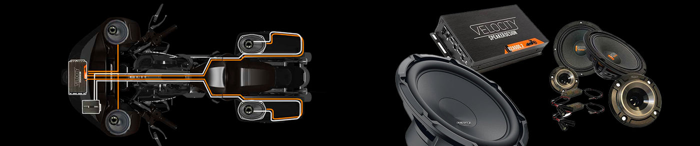
Velocity RZ65H speakers are designed to be used with a digital sound processor to achieve both extreme output as well as exceptional frequency response. These speakers will perform much better than other pro-audio type speakers even without a DSP, but a DSP should always be used to get maximum performance.
Equalization Details
Equalization settings are critical to the performance of your speakers. In the screenshot below you can find the equalization settings in detail. Here is a link to the full resolution image:

Important Notes
Graphic EQ Settings
Bands 16 through 29 use graphic equalization only. Meaning that the center frequencies are standard for a 31-band EQ and the Q factor for each band is 4.32 (1/3rd octave). These adjustments can be done on any standard 31-band EQ with any DSP. These adjustments will yield a smooth frequency response when the woofer and horn tweeter are used together along with the included passive crossover. Copy these settings to your DSP for instant results. These settings have been carefully crafted to level out the response of these speakers.
Optional Parametric EQ Settings
Bands 1 through 5 are optional adjustments. These bands have had their center frequencies and Q factors re-adjusted. These frequency adjustments have been re- assigned to overlap the graphic EQ bands and can be used to add a personal taste or application-specific adjustment on top of the graphic equalization without disturbing the fine detailed adjustments in the graphic equalization. This in effect gives you a second 5-band equalizer. If these bands are not used, the graphic equalization will still yield a smooth and desirable response.
Important Note
Parametric settings should be used with caution and moderation. Adding large amounts of positive gain will add huge amounts of extra burden to both the amplifier as well as the speakers. Always reset the amplifier’s gain after making any changes to the speaker’s equalization. Especially when changing parametric equalization. Below is a brief description of how to make use of each of the 5 parametric bands.
Close up of Optional 5 Parametric Bands

Band 1. - 200HZ
This band has a Q factor of 1.4 which is one full octave. This band can be used to add or remove the lowest frequencies from the 6.5” woofers. Adding any boost to this band will result in added cone excursion and amplifier demand which in turn reduces the high volume ability of the speaker. This band can be used if the speakers are not reaching their mechanical limitations at the system’s full volume level. If however, you are finding that the speakers are reaching or exceeding their mechanical limitations, this adjustment should be set to zero gain. Another option is to reduce the speaker channels output gain by an equal amount to any gain you add to band 1. This will null out any added burden on the speaker while still giving you control over the speaker’s low end frequency response. When doing this you are trading off the speaker’s output in favor of low- frequency response.
Band 2. - 500HZ
With a Q factor of .05 this band covers multiple octaves. This is a very wide frequency adjustment. This band affects the lower human vocal range often referred to as the mud range. It can be used to add or remove some extra presence and boldness to vocals. Use caution as too much output in this range can cause speaker cone break up which is a very audible distortion in the mid-bass range.
Band 3. - 1kHZ
With a Q factor of .05 this band covers multiple octaves. This is also a very wide frequency adjustment. This band covers the middle to high end of vocals. Too little output in this range leaves the system sounding hollow and too much output makes the system sound nasal.
Band 4. - 7kHZ
With a Q factor of 0.5 this is also a very wide adjustment. This single band can be used to make the entire high- frequency range more or less bright without compromising all of the fine detailed graphic EQ adjustments. Be sure to listen to multiple music tracks when making this adjustment (as you should do with all adjustments). Too much positive gain on this band will result in a lot of extra burden on the tweeters which can then lead to burned voice coils. Use to set the high-frequency level to your taste but use it with caution and moderation.
Band 5. - 10kHZ
With a Q factor of 0.5 this is also a very wide adjustment. This band is useful for adding a bit of sparkle to a system that is plenty loud on the high end but still sounds dull. Whenever using this adjustment it is a good idea to play with a balance of band 4 and band 5 (or even better, use only one or the other) since they overlap each other. Adding too much gain to either or both bands is a really bad idea as it will almost certainly result in an unbalanced hissy sound and will definitely overburden the tweeters and result in damage. This band is useful in compensating for obstructions in the tweeter’s path such as tall bars or an off- axis situation such as an installation in lowers.
Passive Crossover Connections

The RZ65H coax horn is a true woofer and tweeter component set mounted on a common frame. The electrical connections for the horn and the woofer are discrete. The RZ65H speaker has two sets of connection terminals. The spring-loaded terminals attached to the speaker frame are for the 6.5” woofer and the spade terminals on the rear of the magnet are for the horn tweeter. The included passive crossover must be connected between the horn and the amplifier. The woofer should be connected directly to the amplifier and does not require any filter from a passive crossover. Both the horn and the woofer should be connected in parallel to the same amplifier channel as shown in the illustration. The easy way to do this is to simply connect the passive crossover input connections to the woofer terminals along with the amplifier connections. This puts the horn tweeter in parallel with the woofer.
Caution!
The passive crossover must not be oriented in a way that the coil in the crossover is directly in the magnetic field of the speaker. Notice that the crossover coil is attracted to the speaker magnet. The crossover should be positioned in a way that the coil is not under influence of the magnetic field. If the crossover is too close to the magnetic field the crossover will not function as it should, the speaker system will not sound correct, and the final impedance of the speaker will be much lower than it should be, which can cause amplifier issues.
High Pass Active Crossover Settings
Crossovers built into amplifiers and digital sound processors are referred to as active crossovers. The RZ65H must be high-passed either at the amplifier or at the DSP. DSP crossovers are always recommended over the amplifier crossovers and a crossover slope of 24db is always recommended over a 12 db slope. Amplifier crossovers are almost always 12db and most DSPs have a 24db option. Never use both the amplifier and DSP crossovers. It needs to be one or the other in order to avoid signal phase issues and frequency gaps. High pass frequency will vary between 100 and 150hz depending on the application. Systems with other larger speakers should use a crossover frequency of 150hz whereas systems with only 6.5” speakers may opt for a lower crossover frequency.
ALL High SPL Systems
should always use a 150hz crossover frequency. Remember that the lower the crossover frequency the lower the total speaker output is without the danger of overloading the speaker. A lower crossover frequency puts a much greater demand on the speaker’s cone movement and also generates much higher levels of heat in the voice coil. Overheated voice coils will cause failure and are not a result of a manufacturing defect. Burned voice coils void the speaker’s warranty.
Setting Amplifier Gain
Incorrect amplifier gain will lead to poor performance and possibly a burned voice coil which is not a manufacturing defect and is not covered under warranty. So the goal is to get it right the first time. Amplifier gain should always be set for the speaker’s mechanical limits and never for a target power number. Amplifier gain should never be set for the speaker’s RMS or Peak power rating. These are thermal ratings and have nothing to do with a speaker’s maximum or optimum power requirements. A speaker’s maximum power capabilities are determined by mechanical limitations. Once Xmax has been achieved (maximum linear cone excursion) there is nomore volume or performance to be gained. Fortunately, a speaker’s mechanical limitations are far below its thermal limitations. By correctly setting your amplifier gains and practicing a little common sense, you should not run into thermal issues.
We Make It Easy!

Support
1(888) 311-0016
4121 Citrus Ave
Suite 1
Rocklin, CA 95677
Warranty Registration
RZ65H Specs

Crossover Frequency

Feel free to contact us with any questions you might have.
American Hard Bag
4121 Citrus Ave., Suite 1
Rocklin, CA 95677
(888) 311-0016
americanhardbag@gmail.com
We at American Hard Bag provide the Manual Installation Guide for this item in PDF format, click the button and save the file.
Back to the page installation guide