Back to the page installation guide.
WH-14-PNP-R Harley Radio Rear RCA Kit
Clean rear-channel signal pickup for Harley touring audio systems. This guide covers rear harness connection, amplifier hookup, radio flash requirements, testing, and the optional high-level input modification path.

Kit overview
The WH-14-PNP-R is designed to pick up the bike’s rear speaker signal and feed it to an aftermarket amplifier using RCA-style inputs while retaining a clean, install-friendly connection path. It is the rear-channel companion to the WH-14-PNP-F front harness.
Tools & parts
Tools required
- Torx drivers for fairing removal, if needed
- Panel removal tools
- Digital multimeter
- Electrical tape or heat shrink tubing
- Zip ties for harness management, optional
Parts
- Included: WH-14-PNP-R harness with RCA adapters
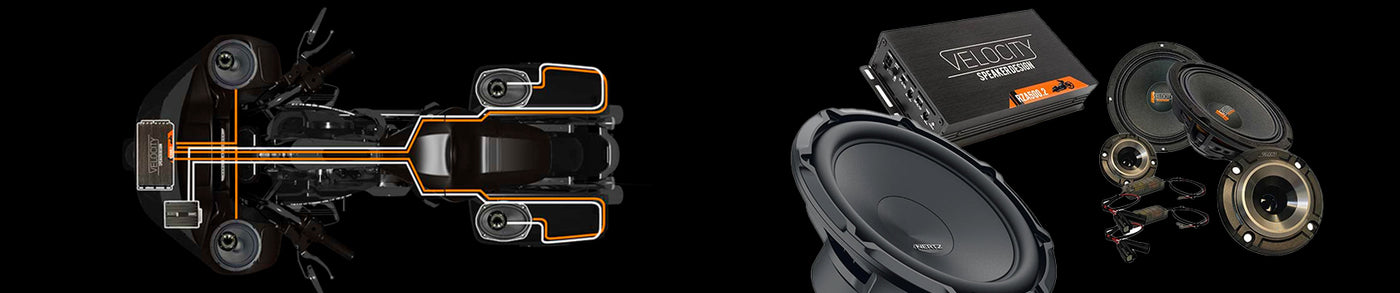
- Recommended pairing: Velocity amplifier systems
- Companion harness: WH-14-PNP-F for front channels
This harness is commonly used when adding aftermarket rear amplification to Harley touring bikes and pairs cleanly with Velocity audio upgrades.
Installation steps
The WH-14-PNP-R connects at the radio rear output connection point inside the fairing.

1
Locate the radio rear output connection
Identify the rear output connection point inside the fairing.
⌃
Identify the rear output connection point inside the fairing.
Use Figure 2 as your reference. The WH-14-PNP-R installs at the radio rear output connection point.
2
Disconnect the factory rear output connector
Unplug the rear output connector from the radio.
⌃
Unplug the rear output connector from the radio.
This creates the insertion point for the WH-14-PNP-R harness.
3
Connect the WH-14-PNP-R inline
Plug the harness between the radio and the factory connector.
⌃
Plug the harness between the radio and the factory connector.
- Connect the harness to the radio rear output
- Connect the opposite side to the factory rear output plug
Make sure all plugs seat fully before routing the RCA leads.
4
Route the RCA outputs to the amplifier
Run the RCA leads cleanly to the amp location.
⌃
Run the RCA leads cleanly to the amp location.
- Black RCA = left rear channel
- Red RCA = right rear channel
Connect these to the appropriate rear inputs on your amplifier, commonly channels 3 and 4 on a 4-channel setup.
5
Secure all harness routing
Protect the install from vibration, rubbing, and pinch points.
⌃
Protect the install from vibration, rubbing, and pinch points.
Tie the harness up cleanly and keep it away from sharp edges, moving parts, and tight pressure points inside the fairing.
Radio flash explained
A radio flash is a software update to the factory Harley radio using the TechnoResearch tool. When adding aftermarket amplifiers and speakers, the flash tells the radio the factory setup has changed and optimizes the signal path for the upgraded system.
Amplifier compatibility
The WH-14-PNP-R outputs a speaker-level signal over RCA connectors. Many motorcycle amplifiers accept this directly, including many Velocity amplifier setups, but not every amplifier does.
How to confirm compatibility
- Check the amplifier manual for support of speaker-level input over RCA.
- Use a digital multimeter and measure resistance between the outer rings of the RCA inputs. A compatible amplifier should generally show resistance in the thousands of ohms.
- If the reading is near zero ohms, the RCA input is likely line-level only and not appropriate for the standard WH-14-PNP-R connection method.
If the amplifier is not compatible with speaker-level over RCA, use the optional modification method below.
Optional harness modification for incompatible amplifiers
This section is not part of the normal installation. Only use it if your amplifier does not support speaker-level-over-RCA input.


A
Cut off the RCA connectors
Follow the cut locations shown in Figure 3.
⌃
Follow the cut locations shown in Figure 3.
Make clean cuts and leave enough wire length to connect into the amplifier’s high-level input pigtail.
B
Remove the resistor section
Delete the resistor portion exactly as shown in Figure 3.
⌃
Delete the resistor portion exactly as shown in Figure 3.
This prepares the harness for direct wire-to-wire connection into the amplifier’s high-level input harness.
C
Match the wires by channel and polarity
Use the color map in Figure 4 before making final connections.
⌃
Use the color map in Figure 4 before making final connections.
- White = Left positive
- Green = Left negative
- Red = Right positive
- Black = Right negative
D
Connect to the amplifier’s high-level input pigtail
Extend wires if needed and secure all final splices properly.
⌃
Extend wires if needed and secure all final splices properly.
- Crimp or solder all final connections
- Seal with heat shrink tubing or quality electrical tape
- Secure the modified harness so it cannot chafe or vibrate loose
Verification & testing
- Power on the radio.
- Verify both rear channels produce sound.
- Confirm left and right rear channels are correct.
- Check fader operation from front to rear.
- Bring the volume up gradually and confirm smooth output without distortion.
- Confirm the radio has been flashed using the proper aftermarket audio profile.
Troubleshooting
| Symptom | Likely cause | Recommended fix |
|---|---|---|
| No rear sound | Harness not fully seated at the radio rear output connection. | Disconnect and reconnect both ends of the WH-14-PNP-R until the plugs fully lock in place. |
| Rear channels reversed | Left and right RCA inputs are swapped at the amplifier. | Swap the RCA connections so black is left rear and red is right rear. |
| Weak output or poor fader control | Radio has not been flashed for aftermarket audio configuration. | Flash the radio using the correct profile so rear output and fader behavior work properly. |
| Distorted sound | Amplifier may not support speaker-level signal over RCA. | Verify amplifier compatibility or use the optional high-level input modification method. |
Vehicle fitment
2014-2023 Street Glide
2014-2023 Road Glide
No CVO or Ultra or Tri Glides
Back to the page installation guide